


 Back
BackI've been toying around for a while with an idea for a procedural world generation + simulation project as an experiment in C++ and graphics programming to teach myself more about computer science and rendering techniques. Part of this is, of course, setting up the infrastructure for input handling, world logic, debug menus, and rendering. When writing the initial code, I used the Mandelbrot set for testing. This led me down a rabbit hole of improving my rendering techniques for this application, as well as trying out different fractals, ultimately culminating in this GPU-accelerated fractal explorer (transform, zoom, pan) with progressive refine:
Outline
Fractal Sets
The Mandelbrot Set
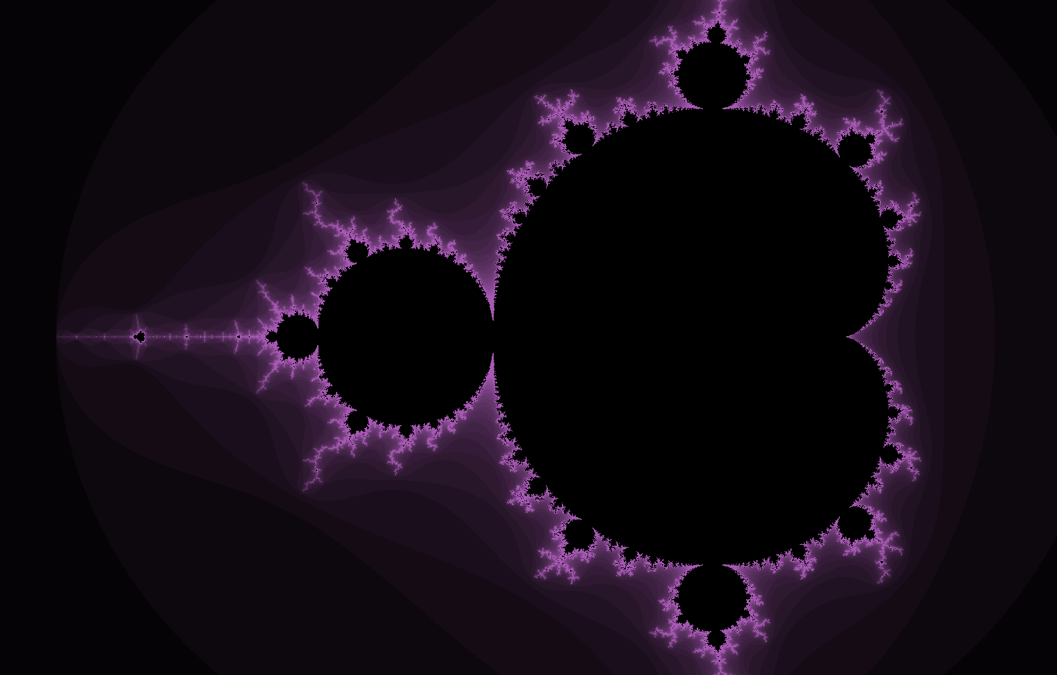
The Mandelbrot set is defined to be the set of all numbers c in the complex plane for which the following sequence (what I call a "z-transform" here — not related to the signal processing Z-transform) does not diverge to infinity:
Note that the z-squared term is squaring a complex number, given by the following:
where a is the real term and b is the imaginary term.
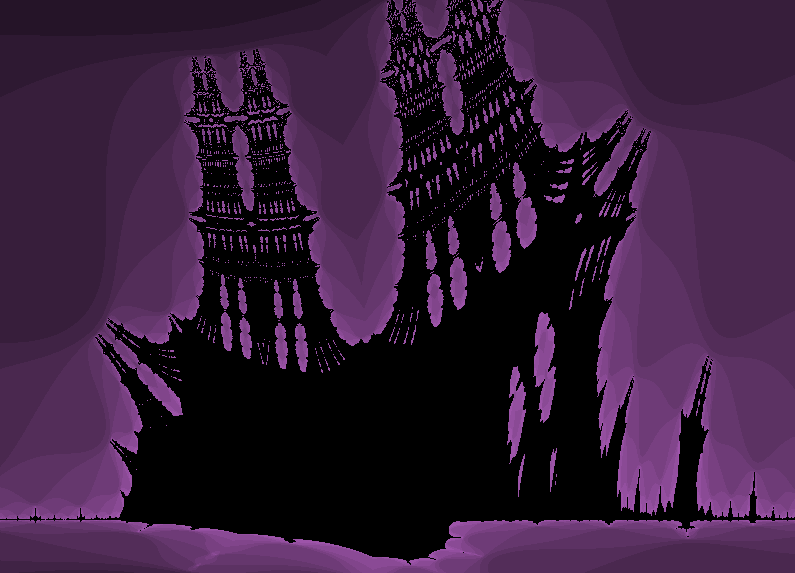
When rendering, we take the real axis to be x and the imaginary axis to be y. Points (numbers) in the set are colored black, and points not in the set are colored with a brightness corresponding to the number of iterations required until divergence.
The above unassuming sequence and rules of complex algebra result in perhaps the most popular fractal shape, which exhibits infinite complexity at the boundary of the set and yields new patterns—including copies and variations of the set itself!—wherever you zoom in, forever.
Needless to say, I've been pretty fascinated by it. This isn't the only fractal set though. You can generate more interesting shapes and patterns by simply modifying the original sequence, or just coming up with something new. You can also add an additional parameter to play around with, transforming fractals. I don't get very scientific with it. You can see this used in the video to transform between fractals. Most random variants however are relatively boring in that they 1. don't produce more than one or two patterns, 2. produce patterns that are just the Mandelbrot set (this by itself is an interesting pattern of emergence), or 3. devolve into noise when zooming in most places. There are a couple exceptions of note:
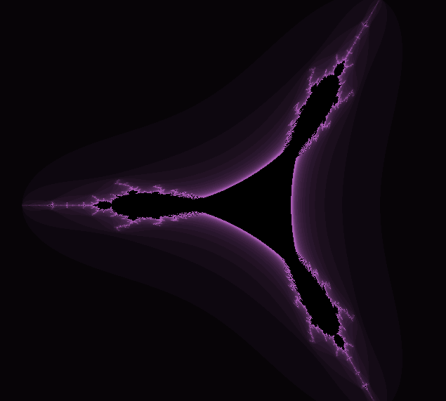
The Tricorn Set
The Tricorn set is a variant of the Mandelbrot set that uses the conjugate of z, which inverts the sign of the imaginary term.
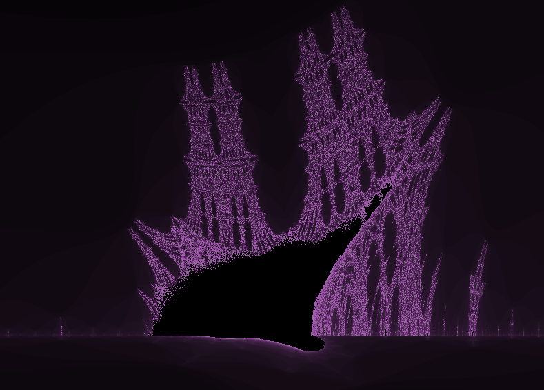
The Burning Ship Fractal
A more well-known variant of the Mandelbrot set is the Burning Ship fractal, which takes the absolute value of z before squaring it.
The most interesting part about this one is actually the figure to the left, which is what the fractal is named after.
Notes on Fractal Computation
I want to talk about some details of computing and rendering fractals. As you would expect, for a full quality render you will need to compute iterations for every pixel in the image. This is very computationally expensive. Even more troublesome is having to calculate this for every frame when panning around and zooming in if you're writing a realtime explorer.
Divergence
Let's first define what is meant by "diverge" when iterating over a
z-transform. Mathematically, this means the point is unbounded, or transforms
off to infinity. We can discard a point from the set long before infinity
though—in fact, for the three fractals mentioned above, any complex number with
a distance from the origin greater than 2 will diverge during a z-transform.
Storing the square of this—to prevent having to compute square roots when
applying the Pythagorean theorem—in a discard_threshold_squared constant or
parameter, we can speed things up by stopping before unneeded iterations in our
compute code:
const int discard_threshold_squared = 4;
// [inside z-transform loop]
if ((a*a + b*b) > discard_threshold_squared)
{
    // [store current iteration count for purpose of
    // coloring, indicating point is not in set]
    break;
}
Points in the set will not exit the sequence early. An implication of this is that the more points in the set the frame contains, the longer the frame will take to render.
Iteration Count
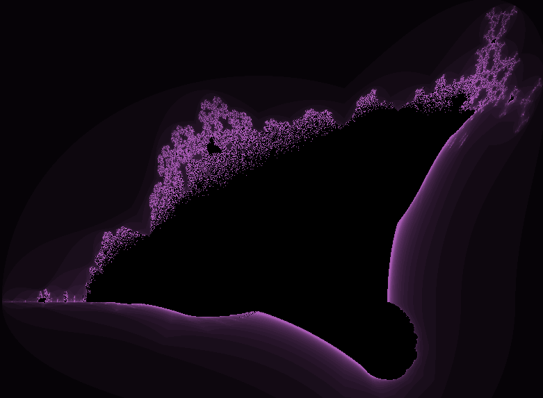
We also need to define a maximum iteration count, the number of iterations it takes to confidently say "this point does not diverge." This makes for another design consideration, though. Note in the screenshots above how points closer to the set are brighter; this means it takes more iterations for those points to diverge. From this, it should follow that increasing the maximum number of iterations will lead to greater detail at the bounds of the set. If we set the iteration count too low, we get undetailed renders like the following (compare to previous screenshot).
Not only that, but zooming in only makes the boundary seem coarser. To
compensate for this, I define my maximum iteration count to be a function of
zoom level, where n0 is a "base" iteration count parameter and s is the
scale (decreases when zooming in).
This largely fixes the coarseness of the shape when zooming in, but poses a new issue. At a certain point when zooming in, the iteration count will become so large that framerate begins to drop. In the Rendering on the GPU section I detail a rendering method called interlacing (or progressive refine) that lets us split up the work of a render across multiple frames.
Floating-Point Precision
The primary limitation with a realtime fractal renderer like this is computer hardware architecture. For most applications, computers store decimal numbers according to standard IEEE 754 (or variants thereof), which, in essence, represent decimal numbers in scientific notation form, comprising a significand ("mantissa") and an exponent. On modern CPUs and GPUs, there are floating-point arithmetic units (FPUs) built into hardware that make computation with floating-point types significantly faster than it would be with a software-only implementation. FPUs nowadays come in sizes of 16 bits (half-width/FP16), 32 bits (single-width/FP32), 64 bits (double-width/FP64), and 128 bits (quad-width/FP128). As you might be able to guess, more bits means larger values means greater precision.
This pertains to computing fractals because the points needed on the complex plane are decimals, not integers. Zooming into one point—effectively increasing the number of decimal places encoded by each pixel's location—only increases the precision required in computing.
Limiting ourselves to hardware floating-point implementations caps our
precision at FP128. In reality, if we're running this on the GPU, we're capped
to FP64, since most GPU architectures don't support FP128. (OpenGL's shader
language doesn't even provide a quad-width type, e.g. long double. Even for
CPU architectures, hardware support for FP128 is
iffy.)
Also, since graphics applications generally don't need more than 32 bits of
floating-point precision, GPUs tend to have only 32-bit wide FPUs, with a slow
processing path for FP64 (about 1/64 the speed of FP32 according to some
benchmarks). Despite this, GPUs have significantly more floating-point
execution units than CPUs, so we're still running faster on the GPU.
With 64-bit precision on the GPU, we can zoom in by a factor of about 14 times before we hit our precision limit.
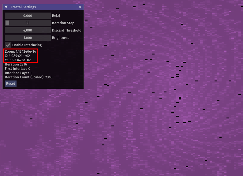
This isn't ideal but it's the best I could come up with (or cared to, considering this was not a planned project) for a realtime renderer. Fractal dive renderers use high-level CPU software implementations for arbitrary-precision floating-point computation, like BigFloat, but this would be disastrously slow for a realtime application (and be incompatible with GPU acceleration).
Rendering on the GPU
Using a Fragment Shader
The 10,000-foot view of the basic OpenGL rendering pipeline for an object is as follows:
- You give the graphics card mesh data and some arbitrary program-defined render settings
- A vertex shader interprets this mesh data as primitive shapes, e.g. triangles, and applies perspective transformations to scale, rotate, and position them relative to the screen or "camera"
- A fragment shader uses the geometry of the primitive plus the given arbitrary render settings (including textures) to fill in the colors of fragments (pixels, basically) within the primitive
- The graphics card does some linear algebra magic to combine the computed data for all objects into a rendered scene, the framebuffer
Knowing my CPU would be too slow for realtime rendering, rather than doing fractal computation on the CPU and loading the result into a texture to be displayed by the GPU, my initial attempt used an OpenGL fragment shader to do computation directly on the GPU. It seemed like a good idea; given two triangles filling the entire screen, the fragment shader is executed for every pixel of the frame and outputs a color for that pixel. However, there were some drawbacks:
- Everything was redrawn every frame, even if the user hadn't moved, unnecessarily consuming GPU resources
- This was extraordinarily slow at high iteration counts (high zoom)
- Iterative refine—either splitting iterations across frames or breaking the frame up into chunks—wasn't feasible (or wouldn't be efficient/elegant enough)
Clearly, a different strategy was needed.
Using a Compute Shader
The compute shader is OpenGL's interface for general purpose GPU (GPGPU) programming—analogous to NVIDIA's CUDA, which lets you use a GPU for arbitrary floating-point-intensive computation. Unlike CUDA however, compute shaders provide cross-platform support (including integrated GPUs) and integrate with the rest of the graphics library, for things like accessing textures. Perfect!!
As they're meant to be used for GPGPU programming, compute shaders aren't built into the core OpenGL rendering pipeline. They must be explicitly invoked (dispatched) by the application, separate of the rendering sequence. This is actually great for our renderer because being able to control when computes happen means we can have them run only when they're actually needed (when the user pans, zooms, or transforms).
// inside application C++ "world logic"
// once we determine we need to recompute after some user input, we can do it like this:

// bind texture/image to save computed data in
m_pTexture->BindAsImage();

// upload arbitrary data/settings (x/y position, zoom level, screen size, iteration count)
m_pComputeShaderUniformUploader->UploadUniforms(program);

// do compute across the width and height of the screen split up into 32x32 pixel chunks
glDispatchCompute((m_windowWidth+31)/32, (m_windowHeight+31)/32, 1);
The compute shader looks like this:
#version 460 core

// define the size of the local working group to be 32x32x1
// main() runs every time for each pixel in the 32x32 region
layout (local_size_x = 32, local_size_y = 32, local_size_z = 1) in;

// arbitrary data/settings ("uniforms") uploaded by the application
layout(r32f, binding = 0) uniform image2D texture0;
uniform ivec2 screen_size;
uniform dvec2 offset; // indicates x/y position within the fractal
uniform double scale; // decreases when zooming in
uniform float discard_threshold_squared;
uniform int max_iteration_count;

void main()
{
    // 1. convert screen pixel location to world/graph space
    // 2. run z-transform
    // 3. store iteration count into texture
}
Splitting up the screen into 32x32 chunks is pretty arbitrary. GPUs are very heavily designed for parallelism, so, generally, splitting work up into chunks means things will get done more quickly, but there is an upper limit to this. In my experimentation, 32x32 chunks seemed to work best for whatever reason.
The only data we're storing in the texture during computes is a single number
per pixel: the number of iterations it takes for the pixel's corresponding
point to diverge. The same texture is then fed into the fragment shader during the
rendering stage, which reads these values and spits out colors to the screen
accordingly. -1 can be used to indicate a point that doesn't diverge (in the
set, colored black).
r32f; this indicates a single channel r with
type FP32, though r32i would work just as well here. See
possible formats in OpenGL documentation for glTexImage2D.
Texture creation is managed by the application.This is great and all, but it doesn't really solve the issue with high iteration counts slowing things down. When zooming in a lot, the application becomes so slow that doing anything has a more-than-noticeable input latency (see this in the video around 0:15). This is where we implement a method for progressive refine.
Progressive Refine
Progressive refine is the act of taking an intensive piece of work and breaking it down into multiple chunks over time. This is commonly done in dedicated renderers when you want a preview of a render that will take a while, or in networking when loading images over a slow connection; it quickly gives you an image at, for example, 1/64 full quality, then not-so-quickly an image at 1/32, then 1/16, and so on, with each step taking longer on average than the previous. Inspired by a friend's use of the Bayer matrix for this purpose, I used a similar interlacing pattern defined by the Adam7 algorithm, which splits work in an 8x8 grid across seven steps:
const int ADAM7_MATRIX[8][8] = {
    {1, 6, 4, 6, 2, 6, 4, 6},
    {7, 7, 7, 7, 7, 7, 7, 7},
    {5, 6, 5, 6, 5, 6, 5, 6},
    {7, 7, 7, 7, 7, 7, 7, 7},
    {3, 6, 4, 6, 3, 6, 4, 6},
    {7, 7, 7, 7, 7, 7, 7, 7},
    {5, 6, 5, 6, 5, 6, 5, 6},
    {7, 7, 7, 7, 7, 7, 7, 7},
};
Incorporating this into the fractal renderer, what we can do is pass some number to the compute shader which indicates which step we're on, [1-7]. The compute shader then indexes the above matrix at the pixel's position, compares that value to the instructed interlace step, and only computes if the values are equal.
uniform int interlace_step;
// [in main()]

// 32x32 work group size means we'll have 16 internal 8x8 grids for interlacing.
// Check where the current pixel is within whichever 8x8 grid it falls in:
int relative_pixel_grid_pos_x = gl_LocalInvocationID.x % 8;
int relative_pixel_grid_pos_y = gl_LocalInvocationID.y % 8;

bool do_compute = (ADAM7_MATRIX[relative_pixel_grid_pos_y][relative_pixel_grid_pos_x] == interlace_step);
if (do_compute)
{
    // z-transform
}
For each pixel, the routine then stores either the new computed value or, if nothing was computed, does nothing. Correspondingly, the fragment shader must be updated for this behavior as well. Following step 1, most elements in the texture will still be empty; to prevent the screen from displaying mostly uncomputed pixels (undefined behavior?), we should check whether a pixel has been computed before trying to use it, and use the nearest computed pixel if the first hasn't been.
The resulting behavior is this:
Now, when zooming in at high iteration count, the first compute step is only doing 1/64 (~1.56%) of the computations it normally would, keeping things within the span of a single frame, i.e. preventing framerate drops. This is great for user actions, where zooming and panning happen for as long as the mouse input lasts—potentially hundreds of frames.
Suppose, though, that a single step takes longer than a frame to compute. Well, that's no worry either since compute shaders act independent of the rendering pipeline, so rendering is not being held up by a compute shader still running. Furthermore, to prevent compute dispatches from overlapping, you can make use of asynchronous OpenGL interfaces like fences and memory barriers to prevent dispatching a new compute for the next step until the previous has finished, framerate unaffected.
My implementation can actually take the idea of progressive refine a step further, allowing the point's z-transform itself to be distributed across computes, resulting in multiple interlacing passes. It does this by storing another two elements per pixel in the texture, the real and imaginary components of the z-transform output, for it to pick up with on the start of the next compute. This poses the same precision issues as before, however, considering OpenGL textures only allow you to store elements up to FP32 precision, so it doesn't work very well at high zoom levels. We can work around this by using a separate texture with four elements per pixel: two 32-bit elements for the real component, and two more 32-bit elements for the imaginary component. See floatBitsToInt and related GLSL functions for a way you might accomplish this.